Wednesday 15 August 2012

[11] Quality Management - Revit Drafting

Revit Drafting

To provide a framework in which Revit users can operate to ensure consistency across all projects and offices in the way in which Revit projects are structured and filed.

1 File Naming & Management
1.1. C:\Project Name\\Drawings\\\BIM Models\\\\Revit is the place on the server to save Revit files

1.2. All files shall begin with the project name followed by a description of the part of the project
that the file contains

1.3. Once worksets have been invoked, a Central file is established. The word “central” shall be
appended to the file name. E.g. MCN_Architectural Model_Central.rvt.

1.4. No user shall work directly on a Central file while file sharing is used


2 Saving & Backups
2.1. Save to your Local file at regular intervals (recommended 15 minutes and not more than 30
minutes) and to the Central file as necessary to update for other users.


2.2. At the end of a work session, you must Save to Central and relinquish all worksets that you had editable, and also save to your local file.


2.3. When recommencing work on the local file, ensure that you Reload Latest Worksets to update the local file.


2.4. Backups of your Revit files are kept under the same directory as the file


3 Drawing Management
3.1. As a general rule, there should be one Revit file per building


4 Graphic Standards
4.1. Text and Dimensions

Generally, do not use text or attributes in blocks
  

Case
2 options:


1. 1Use UPPERCASE consistently throughout a project.

1. Use upper and lower case characters as in normal written English as follows:
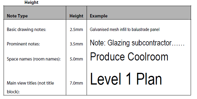
  • Use leading caps at the beginning of complete sentences and proper nouns but not at the beginning of phrases e.g. “tiled floor” not “Tiled floor.”
  • Use caps where special emphasis is required – VERY sparingly
  • Use caps for acronyms and standard abbreviations where caps indicate initialcharacters of separate words e.g. RWP = Rain Water Pipe but not for shortened forms of single words e.g. deg not DEG for degrees.
  • Use caps for labels e.g. BEDROOM, ELEVATION 1.

 Leaders


Dimensions 
The basic dimension shall match the following representation:


[10] Project File Structure

-Project Name
 -ADMIN
          - BIM Management Plan
- DRAWINGS
           - BIM Models
                     - Revit Files
                             MCN_Architectural Model.rvt
                             MCN_Landscape Model.rvt
                             MCN_Interior Model.rvt
                             MCN_Lighting Model.rvt
                             MCN_Structural Model.rvt 
                             MCN_Site Model.rvt 
                     - Superceeded
                             120816 - MCN_Architectural
               - Transfer
                          - Architectural
                          - Current Issue Set
-IMAGES
   - Photoshop
   - Illustrator 
   - Final Images


Collaboration with Dropbox


Sunday 12 August 2012

[9] Week 5 - Project Definition


        Week 5 Group submission
1. As-built (existing) building model
  Revit Models- Architectural, Structural, Services

-Model of existing
  Change all objects to the “Existing” Phase

-Site Plan created from Google Maps

-Orientate project to “True North”
-“Demolish” existing objects that are to be removed
-Create new views for different phases
-Names of files
-Location of files
-Keep log of file sizes for all 6 Revit discipline models and, IFC, IFC optimized files, every week as part of project monitoring
-Log number of IfcBuildingElementProxy objects
-Model Room Check from IES-VE Ware
-Select appropriate materials, building type, building system, and geographic location, and Cooling and Heating Fuel for the existing building and then run IES Analysis. Include pdf IES report
-Run Solibri Model Checker and log results
-Schedule of Areas

2. Design brief response (Text and images)
-Formalise building brief:
a. Total building area to remain the same
b. Create “Area Plans” in Revit to measure the existing areas and create a schedule
c. Building envelope to not be enlarged
d. Stairs and lift to remain
e. Add a third level for apartments and café
f.  Areas
  Ground Floor
  ~1400 sqm: Entry, galleries, shop, office, Workshop
  ~400 sqm courtyard - open to the sky
  First Floor
  ~1000 sqm Studios 5 studios: workspace, entry,   store, kitchenette, WC, shr
  Roof level
  ~600 sqm: Apartments 5 apartments
  Roof top garden, green wall
  ~200 sqm Café
-Formalise  your own project building brief
-Associated rooms that client has not specifically mentioned
-Your understanding of the relationships to achieve the clients   conception 
-Photos for ‘design references
-Spreadsheet of areas or schedule from Revit with some Room data   eg. Level, Room   Name, Area, Finishes
-Preliminary costings use rates from Rawlinsons – Use rates to match   our project Areas from Area Schedules
 -Areas from Area Schedules

-How to measure areas?
“Book of Areas for analysis and comparison of buildings” AIQS

   -GFA – Gross Floor Area
   -FECA – Fully Enclosed Covered Area
   -UCA – Unenclosed Covered Area
   -BA – Building Area or GBA- Gross Building Area
   -UFA – Useable Floor Area
  
   -Common Use Areas
   -Service Areas
   -Non-habitable Areas
   -Area Plans in Revit Architecture

3. Site Analysis (Graphics and text)
-Document site factors
-Add site information to Revit model
-Manage/Project Information
-Environmental criteria

4. Preliminary Concept Design (Graphics)
-Preliminary  design sketches
     -Perhaps better on butter paper or yellow trace
     -What issues have you identified for clarification by the client ?
     -Use Revit graphic capabilities
     -2D
     -3D isometric views
     -Scope Box
     -Perspective (Camera) views
     -Sun / shadows
     -Shaded with edges, Hidden Line, Rendered views
     -Silhouette lines, Gradient backgrounds

5. BIM Management Plan
Template to use, etc…..
 
 NATSPEC documents

 
 a. NATSPEC National BIM Guide
 
 b. NATSPEC Project BIM Brief
 
 c. NATSPEC  Project BIM Management Plan
 
 d. Other reference documents

Submission: Due Thursday the 24th of August 5:00pm

[8] BIM Management Plan

Project MCN Logo


Friday 10 August 2012

[7] Sketch Design Modelling

Sketch design stage check-list:
 
Design Intent:


Changing the sun settings to West End, Brisbane, Australia: 
 

Observing the sun path: 
 

Demolishing and creating voids through the roof in the structural model:


Deleting the existing rooms in the Architectural Model:


Unsuccessful test Renderings, scope boxes and perspective views:


Final Renders:


Concept Diagrams:

Cross Sections:


Longitudinal Sections:


[6] Spatial Planning


[5] Architectural Design

 Required Spaces:
  • Exhibition Spaces
  • Workshops
  • Studios
  • Cafe
  • Courtyard
  • Apartments


Initial Design Sketches:


Ground Floor
  • 1400sqm: Entry, galleries, shop, office workshop
  • 400sqm courtyard - open to the sky


Bubble Diagram illustrating spatial adjacencies and the addition/ amendment of spaces:


First Floor
  • 1000sqm studios: 5 studios: Workspace, entry, store, kitchenette, WC, shr

Bubble Diagram illustrating spatial adjacencies and the addition/ amendment of spaces:


Roof level
  • 600sqm: Apartments: 5 apartments
  • 200sqm cafe  
  • Rooftop garden, green wall
 

Bubble Diagram illustrating spatial adjacencies and the addition/ amendment of spaces: